1 Summarization
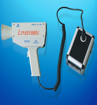
LDR, patrol speed-measuring radar is the latest product of “Landun” radar series of Tongling Landun .Photoelectron Co. Ltd, According to customer requirements, as well as concert technique development, at the base of own former technology, carry out many important improvements and innovations, then developed out it. LDR radar make use of single chip microprocessor to measure and control、 millimeter wave transmitting and receiving system、special program-control filter、automatic calendar clock and mini-printer etc advanced technologies, so Its performance has been improved greatly, and with features of multi-functions、small size、easy operating etc., It lies in the advanced level in the world, and is suited to police、 transportation、freeway、railway etc departments to perform vehicle speed measuring and traffic managing.
1.1 Main function & features
1.1.1 Compatible two work mode stationary (STA) and moving (MOV).
In moving mode, It can measure the speed of host car (carried radar) and target vehicle at same time, can select to measure different direction target —parallel (↑↑) or opposite (↓↑).
1.1.2 The effective distance is far, and the speed-measuring accuracy is high.
1.1.3 The function is complete; with self-check for less-voltage、set up limit-speed threshold 、over-speed alarm、lock and recall、 automatic calendar clock、print for recording and progress control transmitter etc.
1.1.4 Small size、 light weight、 less keys and easy operation.
1.2 The complete set of equipment
| Radar unit | 1 | |
| Packing case | 1 | |
| Special battery pack | 1 | |
| Battery charger | 1 | |
| Standard tuning fork ( high and low frequency) | Each | 1 |
| Operation instruction | 1 |
2 Main performance index
Transmitting frequency : 35GHz
Target speed measuring range :
STA mode 17~180km/h
MOV parallel mode (↑↑) 20~230km/h
MOV opposite mode (↓↑) 20~(255―υpatrol)km/h
Max effective distance (to middle or small vehicle):
STA mode ≥ 600m
MOV parallel(↑↑) ≥ 200m
MOV opposite(↓↑) ≥ 300m
Speed-measuring tolerance:
To STA mode target speed & MOV mode patrol speed ≤1km/h
To MOV mode target speed ≤2km/h
Power supply: 12VDC
Input current
Measuring condition ≤0.8A
Printing condition(average value) 0.4A
Operation environment temp : -30℃~60℃
Radar unit weight : 1.2kg
3 Basic operating principles
When radar transmits a continuous wave signal to target at a fixed frequency, if target moves against radar ( approaching or leaving),The reflect wave that radar receives will occur frequency change, The faster relative moving speed is, The large frequency change of receiving to transmitted will be. This phenomenon is called waves “Doppler effect”, the change amount of frequency caused by it is called “Doppler frequency”, marked as Fd, there is a mathematics relationship between Fd and other variable:
FD=2υ cosθ/λ
Here υ is the compound speed of target speed and patrol speed, unit: m/s;θ is the angle of compound speed vector and electric- axis of radar antenna, it is called measuring angle (see fig1), unit: degree (°); λ is wave-length of transmitting signal, unit: m.
Figure 1
When the wave-length of transmitting signal and measuring angle are fixed, the relationship of Fd and compound speed are direct ratio, linearly. So, as long as to measure out Fd, The radar will be able to calculate the corresponding moving speed. In fact, in high -frequency system of radar, through mixing the frequency of receiving signal and transmitted signal, to obtain Fd signal truly. After it is amplified by wide-band and filter-amplifier, can be provided to microprocessor for measuring and processing.
Through applying appropriate software gate, according to “frequency method”, the microprocessor can measure and calculate to Fd signal, and get out corresponding moving speed.
By program operation, check the state of every switch and button consecutively, to determine radar work mode, and further enter the different program section and math model, based on the filter technology and different math model, it can differentiate and calculate the patrol speed and target speed.
4 Usage methods
4.1 Structure & position diagram, to see figure 2.
Figure 2
1 Target speed screen 2 Patrol speed screen 3 Paper inlet
4 Paper outlet 5 Trigger 6 Adjusting button
7 Clock check switch 8 Red light (same direction measuring) 9 Green light(invert direction measuring) 10 Power switch 11 STA /MOV select 12 Direction(↑↑/↓↑)select 13 Print order
4.2 Main function
4.2.1 Display screen
Be used displaying the speed value measured and relative information. In normal measuring, if no signal, it displays “―”(STA) or “=” (MOV). When there is signal, the above displays the target vehicle speed , and the below displays the patrol car speed. if the left red light is on, indicates that radar hold “MOV↑↑” mode, can measure the parallel vehicle; while if the left green light is on, indicates that radar hold “MOV ↓↑” mode, can measure the opposite vehicle.
When less-voltage take place, the patrol speed screen display “L”.
When trigger is locked, the target speed screen displays the last speed and highest speed of the target alternately.
When set up limit-speed threshold, the target speed screen displays the threshold.
When printing, the patrol speed screen display “P”.
And when clock checking, the above displays calendar and time, the below displays order-number orderly and recurrently.
4.2.2 Switch & button
At the board, The first button from the left is power switch,” press down” is turn on, and “eject up” is turn off.
The second button from the left is mode selection “STA/MOV” key, pressing it one time, the radar operation mode will be changed one time,(monitor by display screen).
The third button is the direction selection(↑↑/↓↑)key., when radar moving, press it one time, the direction of measure will be changed one time also (indicates by red or green light).
The fourth button is printing order key, when press it down, the screen display “p”, radar enter condition of printing data.
The former trigger is locking switch, whenever in speed-measuring or blanking, push it one time, radar enter locking condition, the transmitter is closed, the screen in turn displays the last speed and highest speed measured of this period. push it again, radar come back to the previous condition.
The button in middle of handgrip former is the adjusting button, in condition of measuring, if press it on, to establish the limit-speed threshold, the data displays in screen, when it reaches the expect value, release the button, the threshold value is stored into microprocessor. While clock is checking, if press this button continuously, the time data will be adjusted, and when reaches the correct data, release the button.
The switch in locking board of handgrip is the clock check switch, when need check the clock, push down this switch ,the time data and order number display on screen; to adjust one parameter of time, use the adjusting button, after finished, pull up the switch \put the cover on, and tighten the screw . (notice: under normal conditions, clock tolerance≤1minute/ month, if no evident tolerance, don’t adjust the time system frequently).
4.3 Usage method
4.3.1 The selection of patrol car and the requirement of environment
The wind-screen has certain attenuation and reflection to radar electromagnetic wave, so should select the patrol car with weak attenuation and reflection, it can be determined by measuring and comparing radar act-distance between inside and outside of car in stationary mode.
In the use spot or patrol car, there should be not strong radio or industrial interference, such as high-voltage ignite、fan、air conditioner and radio transmitting etc Interference . If need to communicate by radio, lock up the radar at first.
4.3.2 Start up and check of radar
When used, insert the radar power plunger into the socket of special battery pack.
Turn on the radar power switch, watch the screen, the two lines of digital tube should display “888” at the same time, after 1-2 seconds, the display is blank, and appears“—”or “=”,This means that the radar original procedure is normal and enter the measuring condition .
If the screen displays “L” or “¯L” , shows the battery less- volt, radar will be locked automatically , should stop using and turn off radar at once, then to charge the battery. In this case , to allow using car’s 12v outlet as the radar power.
In the needing time , we can use the conformed standard tuning fork to simulate the examination, strike up the tuning fork to non-metal material (such as wood or plastic),and put it to wave beam in front of radar 10~20 cm, make the plane of fork paralleling the radar axis, As figure 3.
Figure 3
4.3.2.1 In stationary mode, the value displayed in target speed screen should be equal to the fixed value printed in tuning fork surface(±1km/h is normal).
4.3.2.2 In moving , parallel mode (red light brighten),firstly strike up the high frequency tuning fork and put it in beam, the patrol speed screen should display the stander value of this fork, then strike up the low frequency tuning fork, put into the beam of radar also ,the target screen should display the difference of two forks stander value.
4.3.2.3 In moving, opposite mode (green light brighten),firstly, strike up the low frequency tuning fork, and put it into beam, the patrol speed screen should display the stander value of this fork, then strike up the high frequency tuning fork, put it into the beam also, the target screen should display the difference of two forks stander value.
It shows the function of radar speed-measuring is normal.
4.3.3 Normal measuring
Stand on the roadside or sit in the patrol car, makes radar aiming at target vehicle head or end along the radar back , you can measure the speed of moving vehicles.
4.3.3.1 in ” sta” mode (radar is stationary), work mode switch should be set “sta”(only the target speed screen display), the direction switch may be free.
4.3.3.2 In “moving” mode, work mode button should be set to “moving”, if you want to measure the coming vehicle(↓↑), press direction button to make green light brighten, patrol speed and target speed are displayed on the screen at the same time. In this mode(↓↑),the patrol car may runs at normal speed, on the high way, suggest keeping at 70km/h~100 km/h.
4.3.3.3 If want to search and measure parallel vehicle, press direction button to make the red light brighten(↑↑), and accelerate the patrol car, when the patrol car speed exceeds the speed of target vehicle(above 15km/h),the target vehicle speed can be measured out.
Attention: in moving mode,
- a. patrol car and radar must keep stable、 reduce shaking and keep aiming well, if aiming is not good, the max effective distance will decrease.
- b. Before measuring target speed, must firstly measure out patrol car speed, It can be done that when no vehicles in front of patrol car, makes radar aiming at ahead road. If consider that this speed is not correct, in above condition, press down locking trigger two times, to measure again.
4.3.4 Set up limit- speed 、alarming and locking
when radar has measured up the target of over-speed, It will give off “di、di” alarming sound. If you need this alarm, you firstly must establish the limit-speed threshold. In measuring condition, press down the adjustment button, the limit-speed value displayed in target speed screen will increase from 5km/h to 150 km/h, when it displays to the planned value, release the button, limit-speed setting up is finished.
When the target speed value measured is equal to or more than the limit-speed threshold, the buzzer give off alarm. If you don’t want to alarm, you can press adjusting button to increase limit-speed threshold, or start up radar power again.
4.3.5 Printing
Radar can print out the measured data at any time, these data are: limit-speed threshold (if no set up, as 255km/h printing)、inspection times to same target、the highest target speed and respond date、time. Radar can’t measure out vehicle number, only print its title. pay attention to: the time boundary of radar printing data is from lock trigger release or the screen blank( at latest)to now, if no new measuring take place in this period ,keep the date last round.
Start printing, is controlled by operator, if need be, you can press the “printing” key on radar board to start, whether in measuring、after blank or locking. but if no measurement take place after radar starting, no print also. When printing has finished , the buzzer give off “di” sound , then radar come back previous condition.
Before first printing, must insert the paper tape into inlet, tear the record paper must press the paper root at outlet. if paper is tilting, should adjust it at inlet. If printing word is not clear, oil the color tape , or change it.
5 Attentions
5.1 Don’t remove radar shell、antenna and inside parts. If the fuse (insert in power cord plunger) is cut off accidently, after finding out the reason, permit to change it. But other faults happen have to contact with sales department.
5.2 Radar have to use special 12v battery pack as power, permit use 12v cigarette socket of car (the center is positive and the covering is negative pole), but not allow to use other power.
5.3 When radar power pack appear less-voltage, should stop using at once, and charge it by special charger. for 12~14 hours. Don’t allow charge or discharge excessively. Otherwise, it will influence of battery life.
5.4 Radar sense target speed is based on target reflects of electromagnetic wave transmitted by radar, but excessive reflecting energy is able to damage radar receiver. Therefore, prohibit put working radar antenna mouth on the road、floor and vehicle board, prohibit cover the antenna mouth by metal material. In several meters, prohibit use a working radar to aim another radar antenna mouth.
5.5 The measurement tolerance of radar is relative to measurement angle. (See work principle department),if the measurement angle is not appropriate, the measured value will less than real speed. Radar designing request the measurement angle is 0L, it is to say, radar should be on the drive-lane of target vehicle, aim to target head or end. But in fact, for safety reason, it is difficult to follow this. But a small angle, the influence is small also. Through theory calculation, if the angle θ≤6°, the tolerance keeps in -0.55%, it is able to fit the general using request. A question is that the operator how controls this angle? Suppose the vertical distance between radar and target channel is h, the tilted distance between radar and target vehicle is s and the measurement angle is θ, as figure 4.
Figure 4
Through calculating, we can get an experience formula: to the target of outside 10 times h(s≥10h), the measurement angle is inside 6°, For example, if h=4m,then the measurement precision of target speed outside 40m can satisfy prescribed requirement.
5.6 In order to save power, when don’t measure or no target, please turn off the radar , or press the trigger to lock radar. Hope to cultivate a good habit for this.
5.7 please note to avoid vibrating、colliding and dropping,don’t use in raining.
5.8 The illustration about microwave radiation safety
Radar transmit m-m meter electromagnetic wave, the energy mainly focus on the antenna frontier, not harm operator. In outside several meters of radar , The microwave power intensity is inside the state sanitation safety standard .


Reviews
There are no reviews yet.